OS2000 · Installation Manual · Version 2.0
XIMFITX OS2000 Installation Manual
The complete installation of the XIMFITX OS2000 overhead sensor and the XIMFITX simulator software, from unpacking the device to launching your first game. Every camera-based simulation system applies its own installation standards; the procedures here are specific to XIMFITX hardware and software. Follow every step in the order given to achieve the intended accuracy and performance.
Images shown in this manual may differ from the actual product; functionality remains the same.
Installation position video
Before you start
Installation involves working at height and connecting mains power. Use appropriate access equipment and personal protective equipment, and make sure the mains circuit is isolated while the device is being fixed and wired. This document assumes you are comfortable with overhead mechanical fixing, mains electrical connection, and Windows administration.
1Packing List
Do this first. Unpack on a clean, flat surface and confirm every item below is present and undamaged before starting the mechanical installation. Report shortages or transit damage to your supplier before proceeding. Keep the carton and internal packing until the system has been commissioned and signed off — it is the only safe way to return the device if a fault shows up during acceptance testing.
1.1 Supplied items
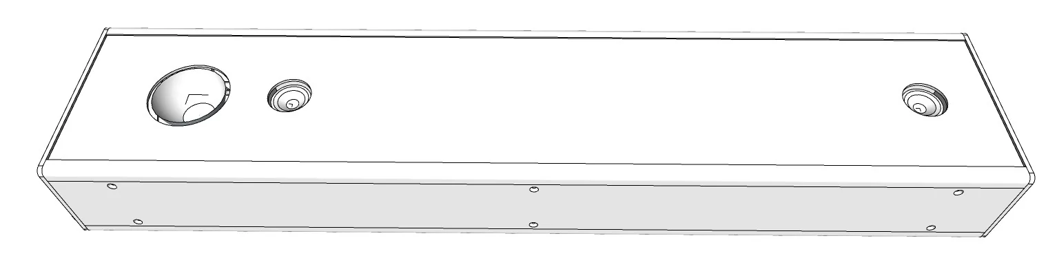
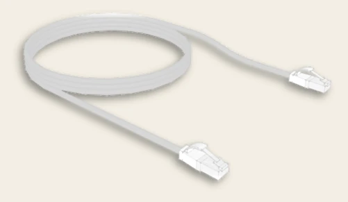
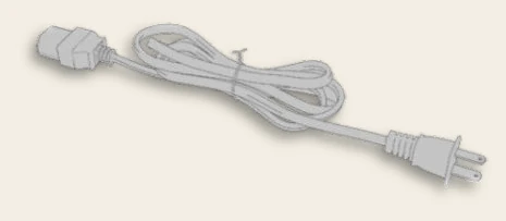
| Item | Qty | Purpose |
|---|---|---|
| OS2000 sensor unit | 1 | Overhead ball and club tracking |
| LAN cable (RJ45) | 1 | Data link between the device and the simulator PC |
| AC power cord | 1 | Mains supply to the device |
| Mounting screws | Set | Fixing the device to the ceiling or to brackets |
1.2 Items you must supply
The following are not included in the carton and must be arranged by the installer:
- A simulator PC meeting the specification in Section 4.
- Ceiling brackets, if the ceiling type requires the bracket mounting method (Section 3.5).
- Two golf balls, and a plumb line or rope reaching from the ceiling to the floor, to set out the mounting position.
- A tape measure, a spirit level, and a marker.
- A mains socket within reach of the supplied power cord, and a network path to the simulator PC.
2Getting to Know Your Device
Understanding the layout of the OS2000 before you lift it into position will save time. Note in particular which face carries the sensors — this face must point downwards toward the tee — and which end carries the connectors and the cooling fan.
2.1 Device layout and connectors
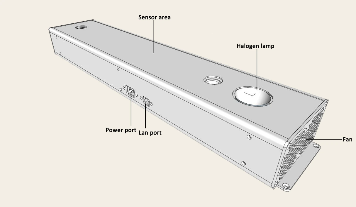
| Feature | Description |
|---|---|
| Sensor area | The camera window that tracks ball and club. It must face the hitting area with an unobstructed line of sight to the tee. Keep this surface clean and free of scratches. |
| Halogen lamp | Provides the illumination the cameras need. Do not obstruct or cover it, and allow it to cool before handling the device after use. |
| Power port | Mains inlet for the supplied AC power cord. |
| LAN port | RJ45 data connection to the simulator PC. Use the supplied LAN cable, or a shielded Cat 5e / Cat 6 cable of adequate length. |
| Fan | Cooling fan at the end of the enclosure. Leave clear air space around it — do not mount the device hard against a wall or bulkhead at the fan end. |
Warning
The halogen lamp becomes hot in normal operation. Disconnect the device from mains power and allow it to cool before adjusting, cleaning, or removing the unit.
2.2 Installation reference data
Keep these figures to hand during the mechanical installation. They are explained in full in Section 3.
| Parameter | Value |
|---|---|
| Mounting height | 2.80 m – 2.95 m from the finished floor |
| Orientation | Perpendicular to the target screen; sensor face pointing down |
| Device set-back from tee line | 15 cm behind the tee line (see Figure 3.3) |
| Tee offset from device centreline | 10 cm (see Figure 3.3) |
| Ceiling requirement | Flat, level and able to carry the weight of the device |
| Fixing points — direct mount | 4 screw holes in the top face |
| Fixing points — bracket mount | 4 × M4 screw holes |
3Hardware Setup
Set out before you drill. The accuracy of every shot the simulator reads depends on the device being in the right place, at the right height, square to the screen. Establish the tee position first, then transfer that position to the ceiling.
3.1 Site requirements
- Ceiling height 2.80 m to 2.95 m. Outside this range the cameras cannot capture ball flight data correctly.
- The ceiling must be flat and level at the mounting position, and structurally capable of carrying the device.
- The device must be perpendicular to the target screen — that is, its long axis runs across the bay, square to the direction of play.
- Clear line of sight. Nothing — netting, lighting, ducting, projector mounts — may sit between the sensor face and the tee.
- A mains socket and a network route to the simulator PC must be available at ceiling level.
3.2 Where to install the device
Decide the tee position first, or install the tee on the floor first. Then mark the ceiling from that tee position using the dimensions in Section 3.3, and install the device. To find the correct position you will need two golf balls and a rope long enough to reach from the ceiling to the floor; this ensures each camera captures your ball flight data correctly.
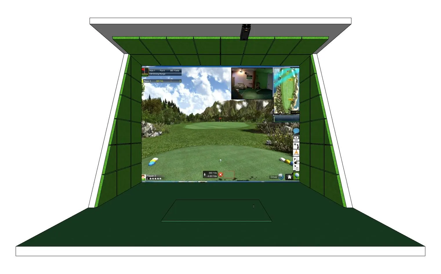
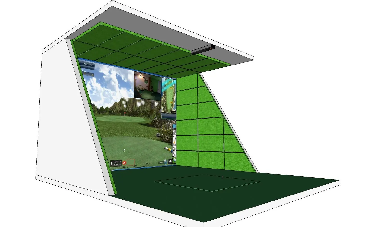
Note
Installation height is measured from the finished floor — including the hitting mat and any raised platform — to the underside of the device.
3.3 Positioning — top view
The plan view below gives the two dimensions that set the device against the tee. Mark these on the floor first, then use a plumb line or rope to transfer the position to the ceiling.
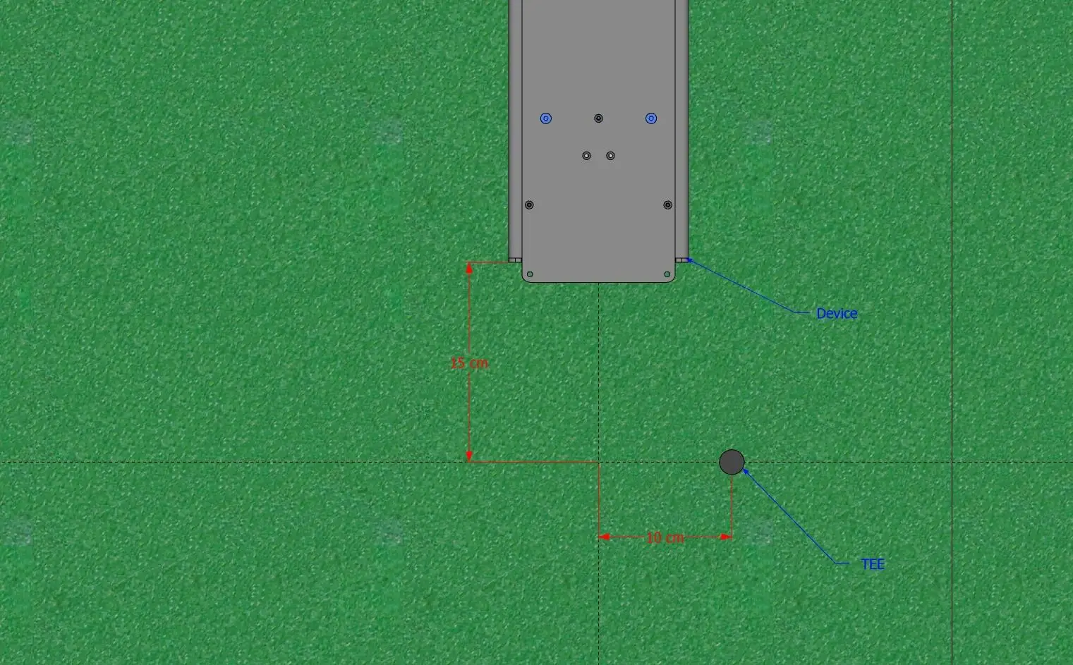
- Fix or mark the tee position on the floor.
- Measure 15 cm back from the tee line and mark this as the device line.
- Measure 10 cm across from the tee to establish the device centreline, as shown in Figure 3.3.
- Use a plumb line or rope from the ceiling to confirm the marks transfer vertically, and mark the ceiling at the fixing positions.
- Check that the marked device line is square to the target screen before drilling.
Tip
Place a golf ball on the tee and a second ball at the marked device line. Sighting along the two balls from the screen is a fast way to confirm the device will sit square before you commit to a fixing.
3.4 Mounting method 1 — direct to the ceiling
Use this method where the ceiling is flat, level and solid enough to take the fixings directly. The top face of the device carries four screw holes for this purpose.
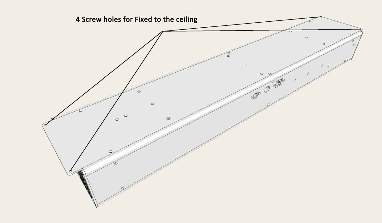
- Transfer the four fixing hole positions from the device to the marked ceiling line.
- Drill and fit anchors appropriate to the ceiling construction.
- Offer the device up with the sensor face pointing down and the connector end toward the cable route.
- Fit all four screws and tighten evenly. Check with a spirit level that the device is level along its length.
- Confirm the finished mounting height is within 2.80 m – 2.95 m.
3.5 Mounting method 2 — ceiling brackets
Where the ceiling is not flat, is a suspended ceiling, or cannot take a direct fixing, mount the device on brackets instead. The device provides four M4 screw holes for bracket attachment.
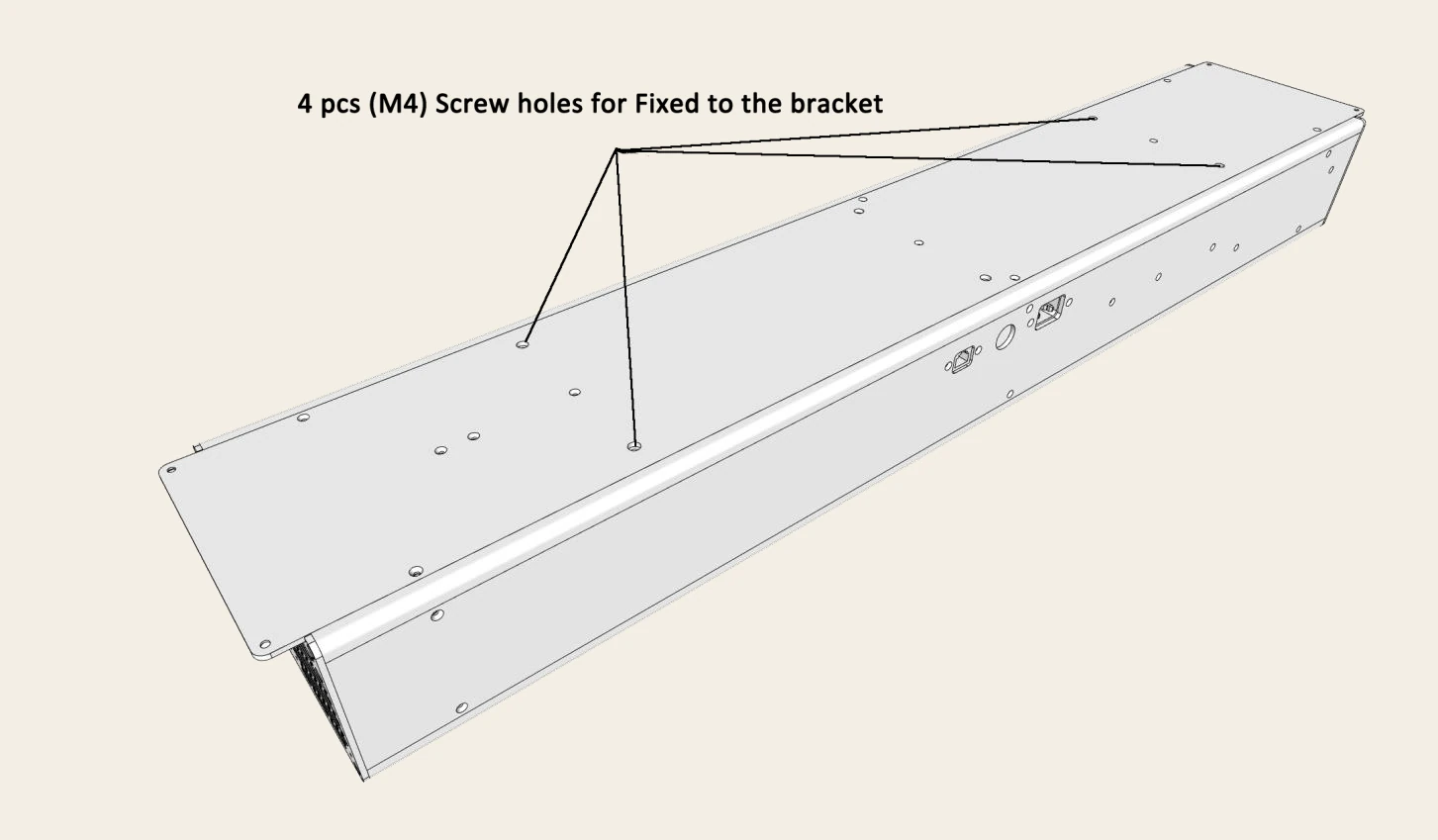
- Fix the brackets to the device using the four M4 screw holes.
- Fix the brackets to the ceiling structure — not to the ceiling tiles or lining — using fixings appropriate to the structure.
- Adjust the brackets so the device is level and square to the screen, then tighten fully.
- Confirm the finished mounting height is within 2.80 m – 2.95 m.
Warning
The device is mounted overhead in an area where clubs are swung. Fixings must be made into sound structure and fully tightened. Never rely on ceiling tiles, plasterboard lining, or a single fixing point.
3.6 Connecting power and network
- With the mains circuit isolated, connect the supplied AC power cord to the device power port.
- Connect the LAN cable between the device LAN port and the network port of the simulator PC.
- Route both cables clear of the hitting area and secure them so they cannot be struck by a club or ball, and cannot obstruct the fan or the sensor face.
- Restore mains power. The device may be left powered off until the software installation in Section 5 is complete.
Note
The OS2000 connects to the PC over a wired LAN connection. A 1 Gbps network port on the simulator PC is required — see Section 4.
3.7 Hardware completion checklist
- Device mounted between 2.80 m and 2.95 m above the finished floor.
- Device level along its length and perpendicular to the target screen.
- Rear edge 15 cm behind the tee line; tee 10 cm from the device centreline.
- Sensor face pointing down, clean, and with clear line of sight to the tee.
- All four fixings made into sound structure and fully tightened.
- Fan end clear of walls and obstructions.
- Power and LAN cables connected, routed clear of the hitting area, and secured.
4Computer Specifications
The simulator PC must meet or exceed the specification below. Under-specified hardware is the most common cause of dropped frames, missed shots, and unreliable camera capture.
4.1 Minimum PC specification
| Component | Requirement |
|---|---|
| Operating system | Windows 11 Professional or Enterprise, 64-bit |
| Processor | Intel Core i7 or above |
| Memory | 8 GB DDR3 or above |
| Storage | 512 GB or above |
| Motherboard | Intel board with USB 3.0 support and a 1 Gbps LAN port |
| Graphics card | NVIDIA GTX 3060 6 GB or above |
| Network card | Intel PCI network card |
| Internet | A working internet connection is mandatory for installation, sign-in, and content downloads |
| Drivers | PCI and motherboard drivers must be up to date — older versions can cause software malfunctions |
4.2 Software policy and security
- Do not install third-party software on the simulator PC. It may harm the simulator system and can slow down the XIMFITX program and the camera capture function. Install only trusted software, and only where genuinely necessary.
- Antivirus: if antivirus software is in use, the XIMFITX application must be allowed through it. Ask your computer supplier or installation engineer to add the exclusion.
- Firewall: if a firewall is in use, all XIMFITX applications must be allowed through it. Otherwise the XIMFITX application will crash at start-up.
- Admin password: you may set an administrator password on the computer for security. This does not affect XIMFITX products.
5Software Setup
Work through the six steps in this section in order. The drivers and runtimes installed in steps 5 and 6 are required before the software is launched for the first time.
5.1 Step 1 — Disable User Account Control
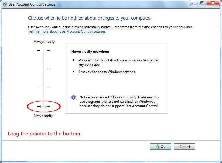
Before starting the installation you must disable the system's UAC (User Account Control) settings.
- Go to Control Panel → User Accounts → Change User Account Control settings.
- Drag the slider all the way down to Never notify, as shown below.
- Click OK, then restart the computer so the change takes effect.
5.2 Step 2 — Download the installer
Download the XIMFITX installer from the address below. Save it somewhere you can find again — the Downloads folder or the desktop is fine.
https://www.bogolf.com/Download/Products/XIMFITX/ximfitx_installer.exe

5.3 Step 3 — Install the software
- Once the download is finished, open the folder where the downloaded file was saved.
- Right-click ximfitx_installer.exe and select Run as administrator.
- The installation wizard opens. Follow the on-screen instructions to complete the installation.
- When the wizard finishes, click Finish.
- A Launch XIMFITX shortcut is created on the desktop. Do not use it yet — several necessary tools still have to be installed.

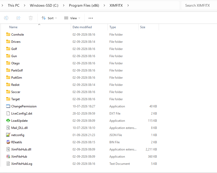
The software installs to C:\Program Files (x86)\XIMFITX. Open that folder and confirm it looks like the illustration above — the game folders, the Drivers and Redist folders, and XimFitxHub.exe should all be present.
5.4 Step 4 — Set the Hub to run as administrator
- Go to C:\Program Files (x86)\XIMFITX.
- Right-click XimFitxHub.exe and select Properties.
- In the Properties window, open the Compatibility tab.
- Tick Run this program as an administrator.
- Click Apply, then OK.
Note
The Hub needs administrator rights to talk to the camera hardware and to write game and course updates into the installation folder. Skipping this step is a common cause of failed updates.
5.5 Step 5 — Install the camera drivers
Warning
Before installing the camera drivers, close all XIMFITX programs — including the XIMFITX Hub — and disconnect the cameras from the computer.
- Go to C:\Program Files (x86)\XIMFITX\Drivers.
- Right-click Camera Platform Setup and select Run as administrator.
- Follow the prompts to complete the driver installation.
- Reconnect the cameras once the driver installation has finished.

Note
XIMFITX supplies several different products and each one uses its own driver. Install only the driver found in the Drivers folder of this installation — it is the one matched to your device.
5.6 Step 6 — Install the Visual Studio runtimes
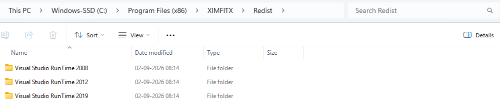
- Go to C:\Program Files (x86)\XIMFITX\Redist.
- Install all of the Visual Studio runtimes present — 2008, 2012 and 2019.
- Run each installer as administrator and accept the defaults.
- Restart the computer once all runtimes have been installed.
6First Launch and Content Download
With the drivers and runtimes in place, the XIMFITX Hub can be started for the first time. The Hub is the launcher for every XIMFITX game and the place where games and courses are downloaded and updated.
6.1 Signing in to the Hub
- Launch the Hub from the Launch XIMFITX desktop shortcut, or run XimFitxHub.exe from C:\Program Files (x86)\XIMFITX.
- The first start takes a few minutes while the setup initialises. Allow it to finish.
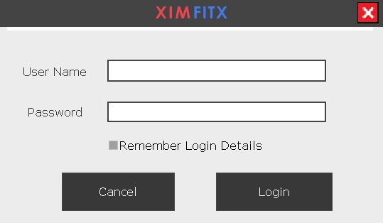
- A login box opens. Enter the User Name and Password supplied with your system and click Login.
- Tick Remember Login Details if you want the Hub to store the credentials so they do not have to be typed at every start.
6.2 The Hub window
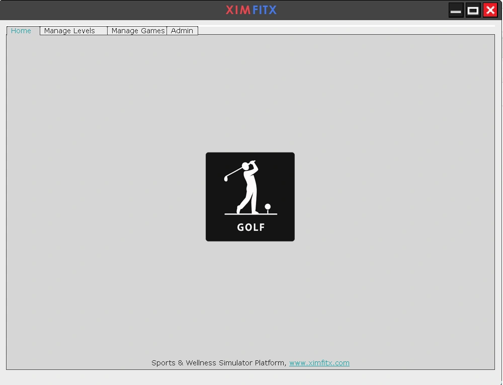
After sign-in the Hub window opens on the Home tab, showing a tile for each installed game. Clicking a tile launches that game. Four tabs run across the top of the window:
| Tab | Purpose |
|---|---|
| Home | Tiles for the installed games. Click a tile to launch a game. |
| Manage Levels | View all levels and courses, and update or download them by sport type. |
| Manage Games | Update, configure, and open the user manual for each game and app. |
| Admin | Password-protected settings — auto login, server selection, and running app status. |
6.3 Manage Games — downloading and updating games
- Open the Admin tab and enter the admin password, then click Allow.
- Open the Manage Games tab.
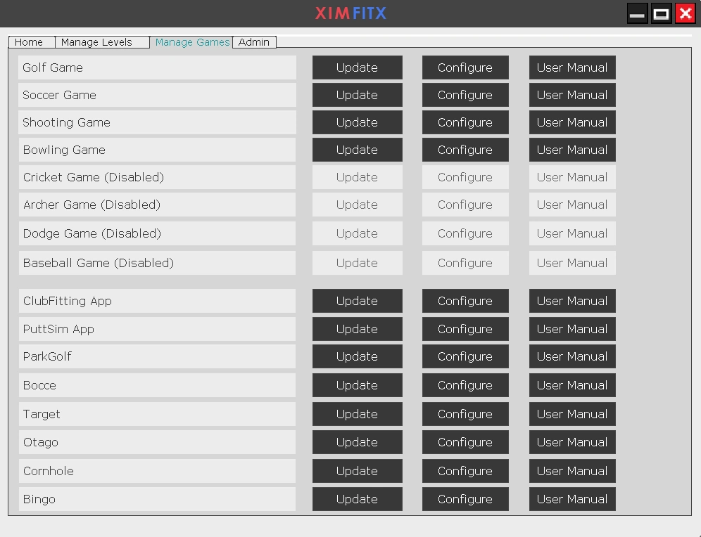
- Find the game you want in the list and click Update to install or update it. Depending on the file size this can take some time — let it run to completion.
- Use Configure to adjust a game's settings, and User Manual to open that game's own manual.
- Repeat for every game the customer has purchased, then return to the Home tab and confirm the new tiles appear.
Note
Games marked (Disabled) are not part of the current licence. Contact XIMFITX if a purchased game appears as disabled.
6.4 Manage Levels — downloading courses
The Manage Levels tab lists all levels and courses available to the system. Select a sport type to filter the list, then update or download the levels the customer requires. Course downloads are large; allow adequate time and a stable internet connection.
6.5 Admin options
| Option | Description |
|---|---|
| Auto Login Setting | Stores the login ID and password on the system. When enabled, the XIMFITX ID and password no longer have to be typed each time the Hub starts. |
| Select China Server | China-based users can select the China server instead of the default US servers. |
| View status of running apps | Shows which XIMFITX applications are currently running — useful when a game appears not to close cleanly. |
7Handover Checklist
Complete this checklist before signing the installation off. Anything left unticked is a callback waiting to happen.
Hardware
- Device mounted at 2.80 m – 2.95 m, level, and square to the screen.
- Set-back and tee offset dimensions verified (15 cm and 10 cm).
- All fixings tight; fan end unobstructed.
- Sensor face clean and unobstructed.
- Power and LAN cables secured clear of the hitting area.
Software
- UAC set to Never notify and the PC restarted.
- XIMFITX software installed to C:\Program Files (x86)\XIMFITX.
- XimFitxHub.exe set to run as administrator.
- Camera Platform Setup driver installed with cameras disconnected, then reconnected.
- All Visual Studio runtimes (2008, 2012, 2019) installed and the PC restarted.
- Antivirus and firewall exclusions added for all XIMFITX applications.
Commissioning
- Hub signs in successfully and reaches the Home tab.
- All purchased games downloaded via Manage Games and visible as tiles.
- Required courses and levels downloaded via Manage Levels.
- Test shots hit from the tee are detected and read correctly.
- Customer shown how to launch games, and given the safety instructions in Section 10.
8Troubleshooting
| Symptom | Check |
|---|---|
| Application crashes at start-up | The firewall is blocking it. Allow all XIMFITX applications through the firewall, and add an antivirus exclusion (Section 4.2). |
| Game or course update fails | Confirm XimFitxHub.exe is set to run as administrator (Section 5.4), and that the internet connection is stable. |
| Cameras not detected | Reinstall Camera Platform Setup with all XIMFITX programs closed and the cameras disconnected, then reconnect them (Section 5.5). |
| Software will not start after a clean install | Confirm every Visual Studio runtime in the Redist folder was installed, not just one (Section 5.6). |
| Shots read inconsistently or are missed | Re-check the mounting height, the 15 cm set-back and 10 cm tee offset, that the device is square to the screen, and that the sensor face is clean and unobstructed (Section 3). |
| Performance is poor or frames drop | Verify the PC meets the specification in Section 4.1, that PCI and motherboard drivers are current, and that no third-party software has been installed. |
| A purchased game shows as (Disabled) | The game is not enabled on the current licence. Contact XIMFITX support. |
| Device does not power on | Check the mains supply and the power cord at the device power port. If the supply is confirmed and the device remains dead, contact your supplier — do not open the enclosure. |
9Product Warranty
Important
The product warranty does not apply in the circumstances listed below. Please read them carefully and make the customer aware of them at handover.
- If the camera or any other hardware received from XIMFITX is damaged or burnt out by a power short circuit, a power problem, or high voltage. Always use a safe power supply.
- If a camera is damaged physically during installation or through mishandling — for example by being hit by a golf ball or a golf club.
- XIMFITX is not responsible for physical injury to any player or person using the simulator. The buyer is responsible for providing safety instructions to all simulator users, or for producing a notice and displaying it in the simulator space. This is an indoor product; players frequently hit wrong shots which may strike a person or an object.
- Do not use additional hardware or third-party software on the simulator computer. It may harm or slow down the simulator software.
10Safety Information
This section contains important information about the operation of your device, and about how to use it safely. Read this information carefully before using the device, and pass it on to the end user at handover.
10.1 Operation
- Follow the documented instructions to shut down the device.
- Turn the device off when it is not in use. Stop using the device if it is overheating. Improper use may lead to malfunction, overheating, or fire.
- The device and its accessories are not intended for use by children. Children should use the device only with adult supervision.
10.2 Care and cleaning
- Keep the sensor area of the device clean, and do not scratch it with hard objects.
- Do not use chemical detergents, powders, or other chemical agents such as alcohol or benzene to clean the device or its accessories. These substances may damage parts or present a fire hazard. Use a clean, soft, dry cloth.
- Before cleaning or maintaining the device, stop using it and disconnect all cables connected to it.
10.3 Environment
- Keep the device and accessories dry. Do not attempt to dry the device with an external heat source.
- Avoid dusty, damp, or dirty environments. Using the device in unclean environments may cause it to malfunction.
- Do not expose the device or its accessories to extreme heat or cold. Harsh environments may interfere with proper functioning and may lead to fire. Ideal operating temperature is 0 °C to 35 °C.
10.4 Impact and damage
Warning
Avoid objects striking the device and cameras. The sensors may break if hit by a golf ball or club. In the event of any breakage, stop using the device immediately. Do not touch or attempt to remove the broken parts — contact the supplier promptly.
- Do not dismantle or remanufacture the device or its accessories. Doing so voids the warranty and releases the manufacturer from liability for damage. In case of damage, contact your supplier for assistance or repair.
11Support
If you cannot resolve an issue using Section 8, contact XIMFITX support through your supplier or via the website. Please have the following information ready — it will get you to an answer considerably faster.
| Information | Where to find it |
|---|---|
| Hardware model | OS2000 |
| Manual version | 2.0 (this document) |
| Software version | XIMFITX Hub — see the Admin tab |
| Installation path | C:\Program Files (x86)\XIMFITX |
| Log file | C:\Program Files (x86)\XIMFITX\XimFitxHubLog.txt |
| Site details | Mounting height, and the set-back and tee offset dimensions used |
Note
Individual game user manuals are available directly from the Hub — open the Manage Games tab and click User Manual next to the game concerned.
Sports & Wellness Simulator Platform — www.ximfitx.com